My Input Output Assignment
This is the GIF of my working fade circuit. So radiant.
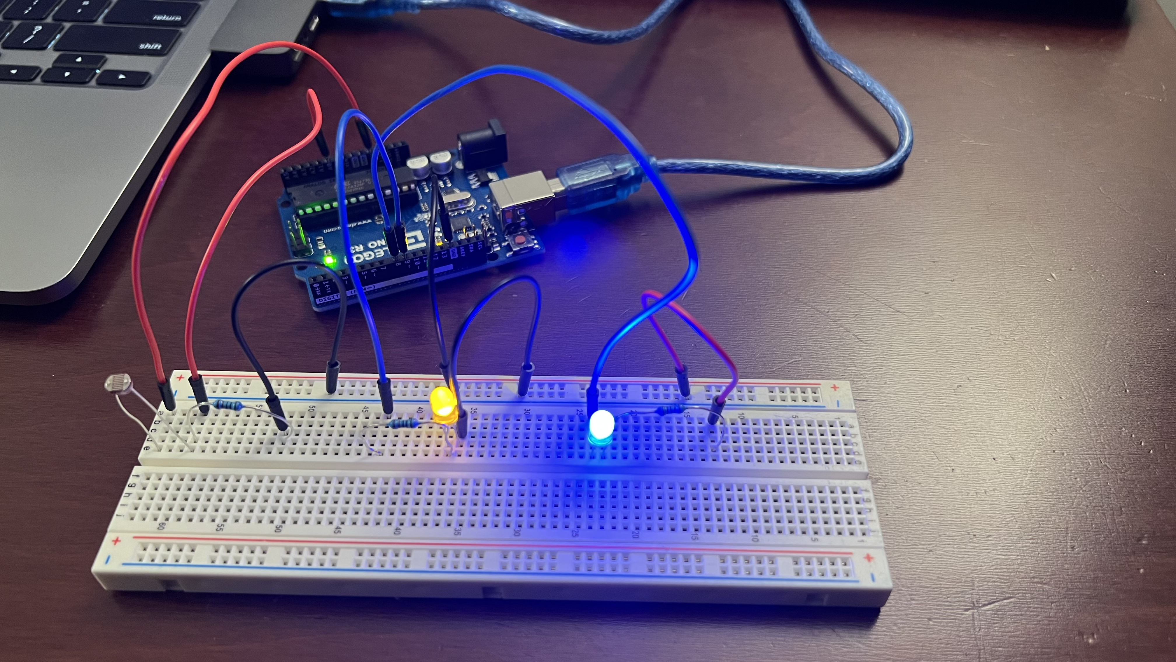
This is a picture of my circuit. I used 220 ohm resistors for both the yellow and blue LED as they provided more than enough resistance for the LEDs to function, they were also the next closest standard I had out. I used a 10K ohm resistor for the voltage divider just to be on the safe side and that was also used in lecture as well.
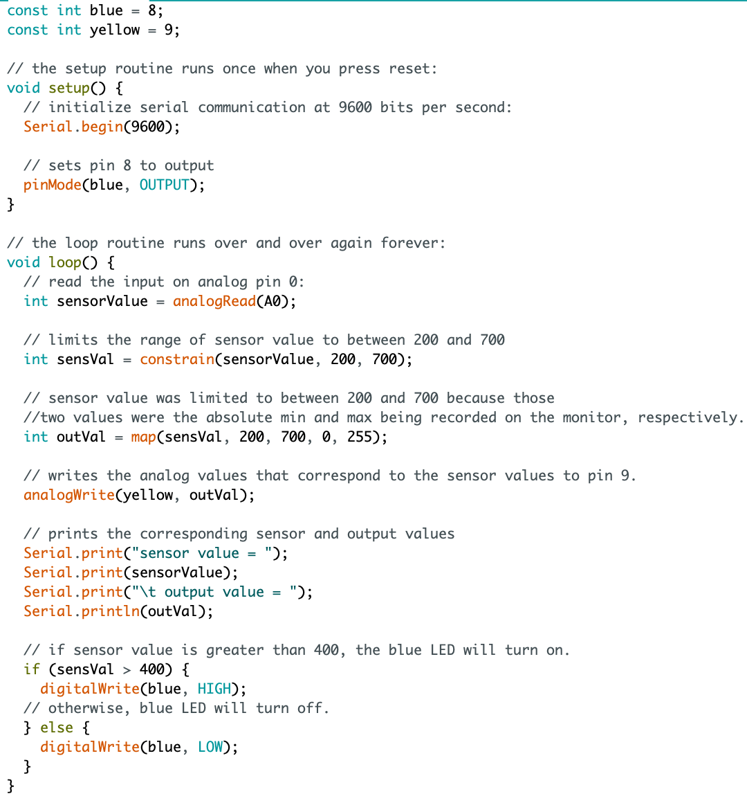
Here is a snippet of my code. All of my important lines of code are commented. I used the values of 200 - 700 as constraints because those were the max and min sensor values that were showing up on the monitor. There was no need to open the range up to 0 - 1024 if it was only between 200 - 700 for values. A sensor value of 200 essentially correlates to 0 on the analogWrite() function which will dim or turn the yellow LED off. A sensor value of 700 correlates to 255 on the analogWrite() function which would turn the LED very bright.
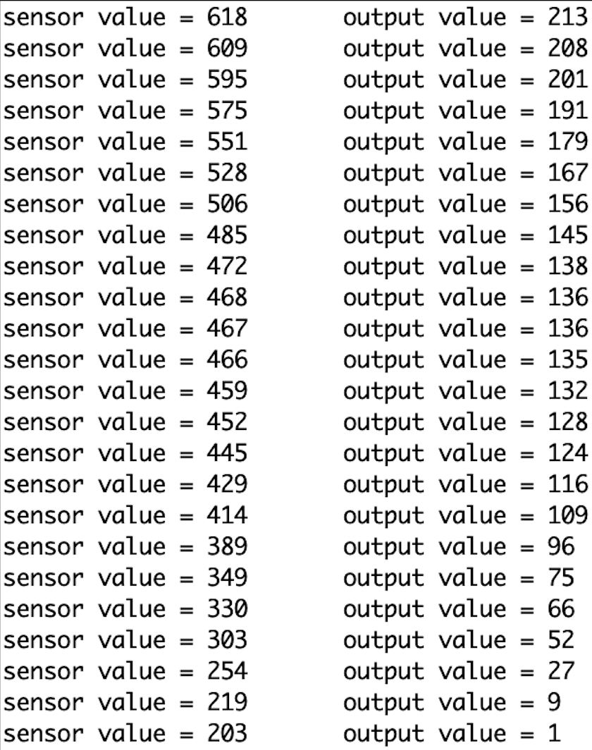
This is the example monitor output when I was running the code and it matches what I said above to the sensor-to-output values.
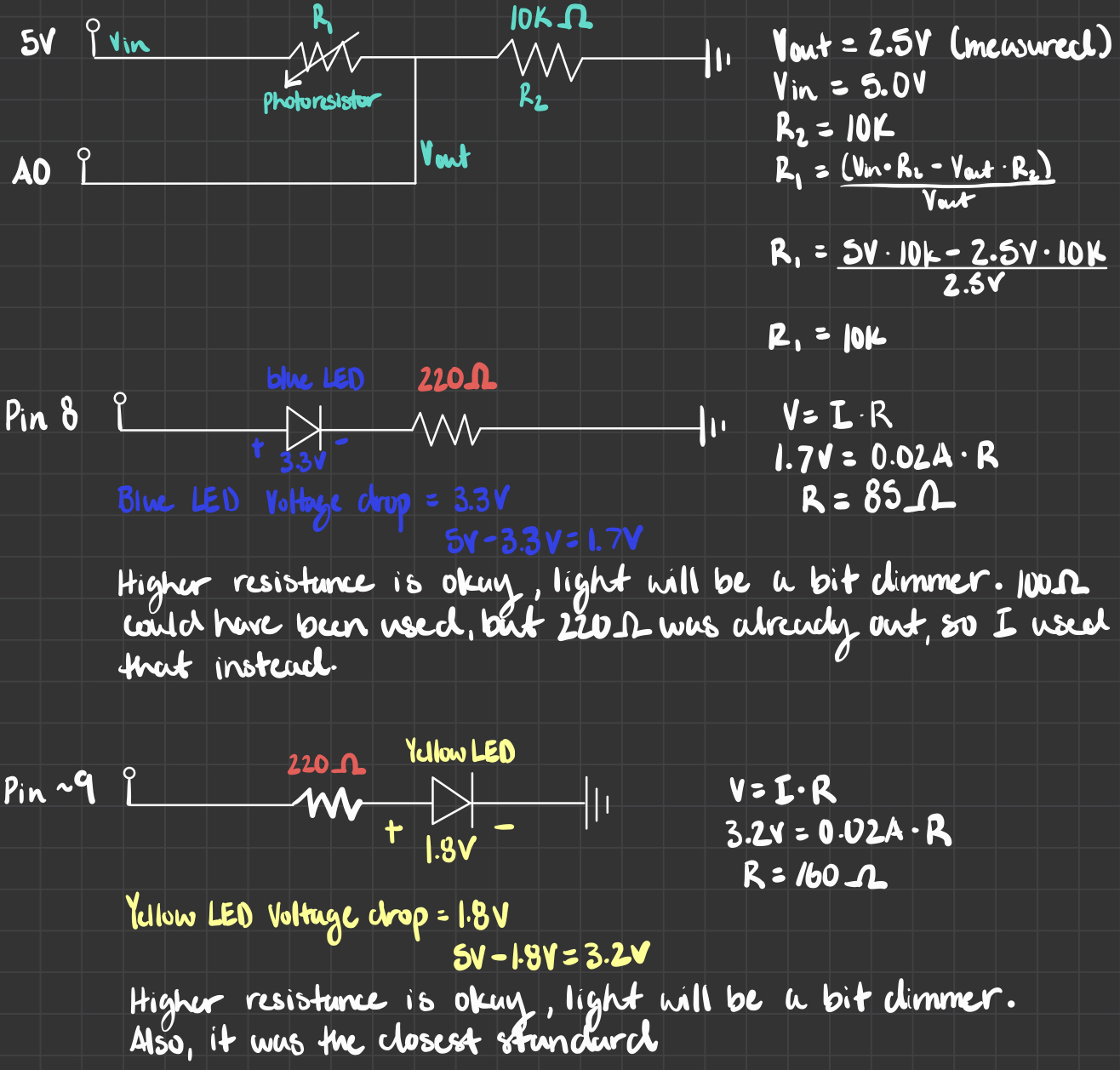
Here is the schematic that I drew up for my fade circuit. All calculations are presented. For the V-out value, I measured it with my multimeter during the running stage and measured 2.5V, so I could determine that the first resistor also had the same resistance because V-in was 5V, so it was a 50-50 split. The calculations for this can be seen. The calculations for the yellow and blue led resistors are also shown.